Part 1: Installing the Motherboard
After you have selected and purchased the parts you wish to use to build your computer, it is time to put it all together.
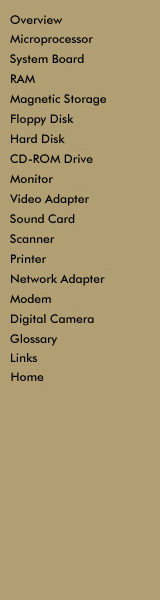
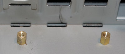
- First, the motherboard must be mounted in the case. The motherboard cannot be screwed directly onto the case, because contact between the metal case and the conductors on the board would result in short circuits that would destroy the board.
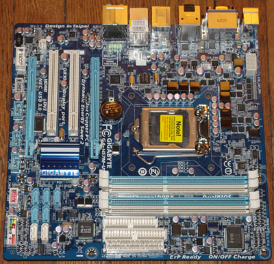
- There are several screw holes in predetermined locations. on the motherboard. The brass standoffs provided with the case, must be screwed securely into the bottom of the case so that they line up precisely with the holes in the motherboard. A standoff in the wrong position will ground the conductors on the board, and prevent the board from working. When everything is lined up correctly, use the screws provided to screw the board securely in place.
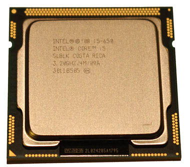
- When the board is secure, it is time to install the microprocessor. The microprocessor must be compatible with the motherboard, and it must be oriented so that the pads or pins on the chip align correctly with the socket. In this example, the Intel Core i5 processor is designed to fit into the LGA 1156 socket on the motherboard. The triangle on the lower left corner of the package indicates the location of pin 1. Note the notches on each side: they are positioned so that the processor will fit in the socket only when aligned correctly.
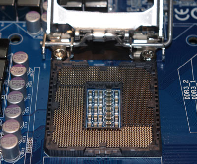
- Raise the load plate by releasing the lever, remove the protective cover, and carefully insert the chip into the socket.
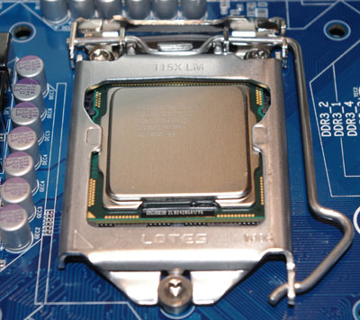
- When the chip is correctly positioned, lower the load plate and secure it by sliding the front tabs under the screw. Close the lever and lock it into position.
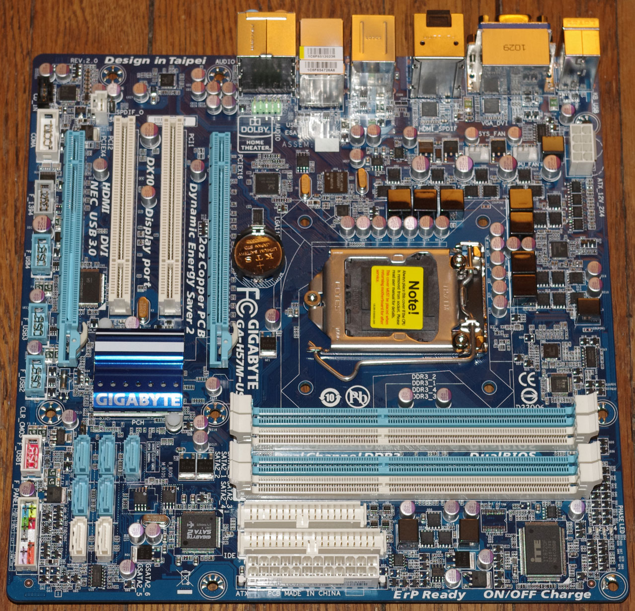
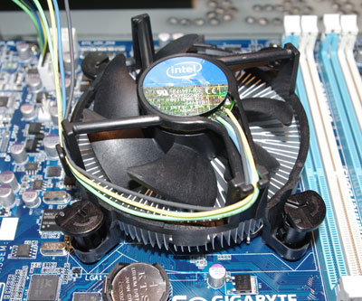
- The CPU cooler is mounted on top of the microprocessor. Before installing it, put a thin, even coating of thermal grease on the cooler or the microprocessor to improve the transfer of heat. There are four push pins (below) that must be inserted into the matching holes in the motherboard(above).
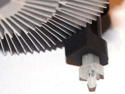
- When the push pins are all inserted, use a slot screwdriver to push them all the way into the hole and then give the pin a quarter turn counterclockwise, in the direction of the arrow on the top of the pin. There should be a click as it locks in place.
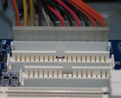
- The next step is to connect power to the motherboard. On a recent model power supply there should be a 24 pin ATX power cable, that plugs into the matching socket on the motherboard as shown below.
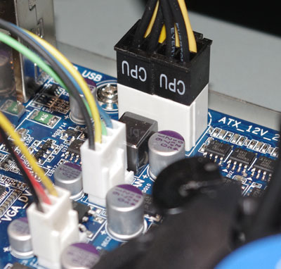
- Most current motherboards also require a separate 12 volt connection for the microprocessor(below). The microprocessor actually operates at voltages in the range of 0.65 to 1.4 volts, but it requires 75 watts of power, so it is more efficient to provide a 12 volt connection to the board and then step it down to the required voltage.
- Plug the power cable from the CPU fan and the case fan into the appropriate sockets on the motherboard as well.
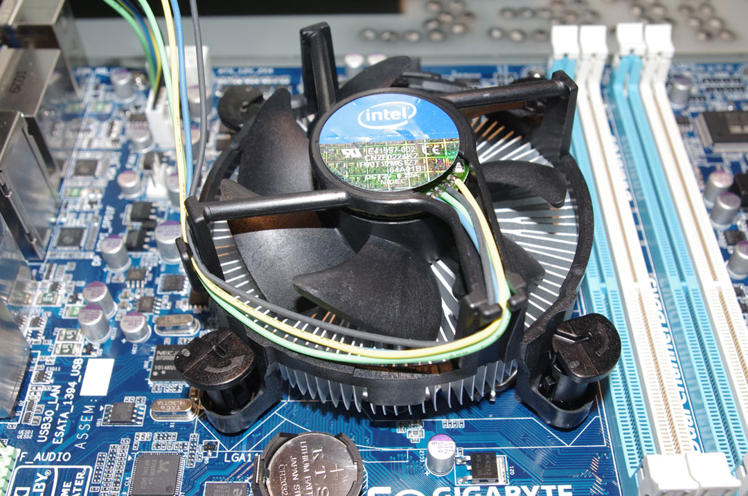
- On one side of the motherboard there will be connection points for the front panel devices, such as the power and reset switches, power indicator lights, and the USB connectors. Identify the cables, and refer to the motherboard manual to determine where they should be plugged in, as shown below.
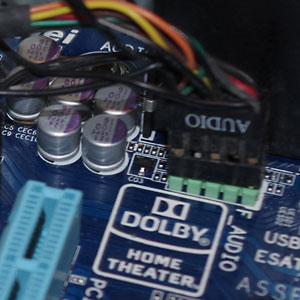
- If your case has front panel audio connections, the audio cable should be plugged into the motherboard if you are planning to use the on-board audio chip. If you will be installling a separate sound card, the cable should be connected to the socket on the sound card.
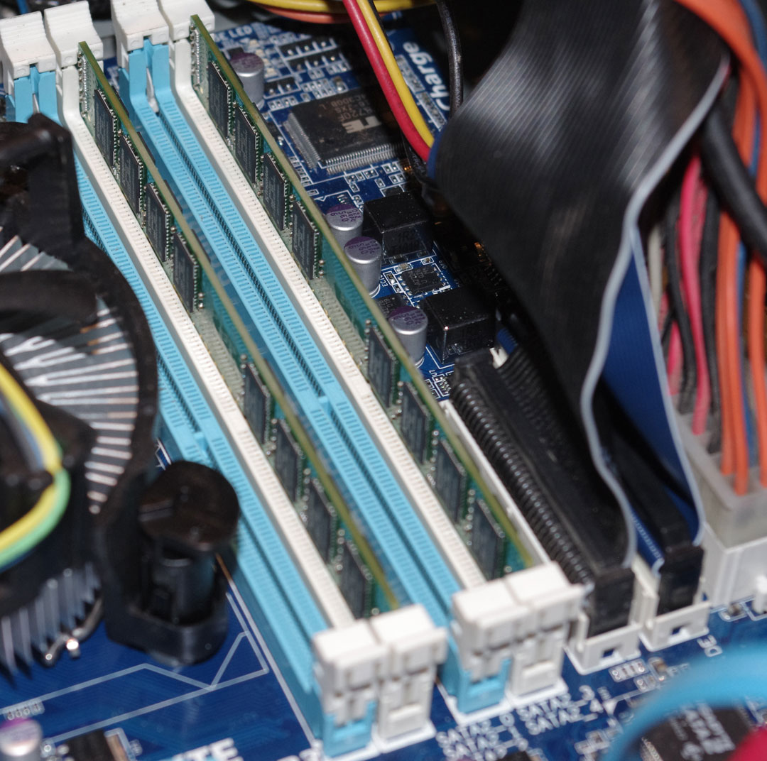
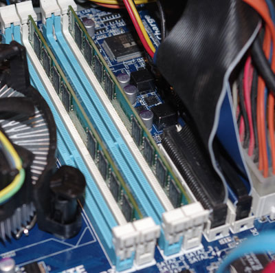
- Depending on the motherboard, there may be one, or two or three pairs of slots known as DIMM (Dual In-line Memory Module) slots. Again, the RAM you purchase must be compatible with the motherboard. In the picture below, two DDR3 modules are shown plugged into slot 1 and slot 3. Consult the motherboard manual to determine which slots to use. To install the module, open the retaining clips, line up the notch in the module with the ridge on the slot, then press down firmly at both ends until the retaining clips snap into position.
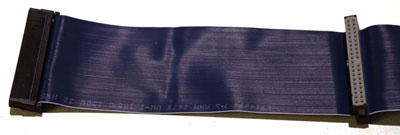
- If you are installing a CD/ROM or DVD, or a hard drive that uses the ATA or EIDE 80 conductor ribbon cable (below), one end of the cable must be plugged into the motherboard, as shown on the picture above. The picture above also shows the floppy drive cable, if your system still has one.
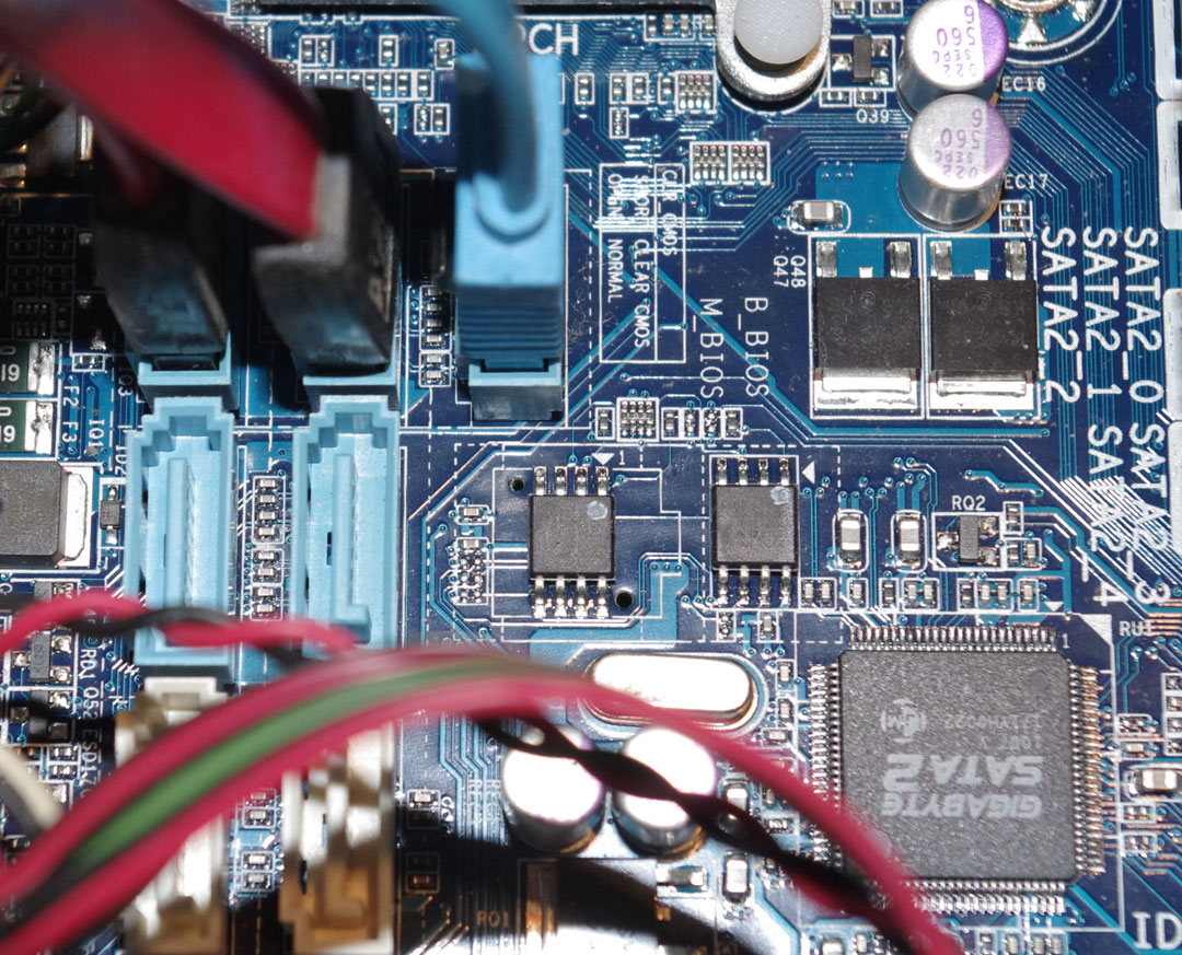
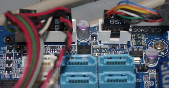
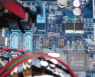
- New hard drives, Blu-Ray drives,and some DVD drives, are connected using SATA (Serial ATA) cables, a seven-conductor cable with a uniquely shaped connector. On the picture below, you can also see a chip with the label SATA2, containing the SATA disk controller. If your drive is second-generation SATA (SATA2), it must be plugged into SATA2 port on the motherboard to get peak performance.
|
|