
System Board
The System Board,
also known as the mainboard or the motherboard is a printed circuit board
which connects all the main components of the computer. 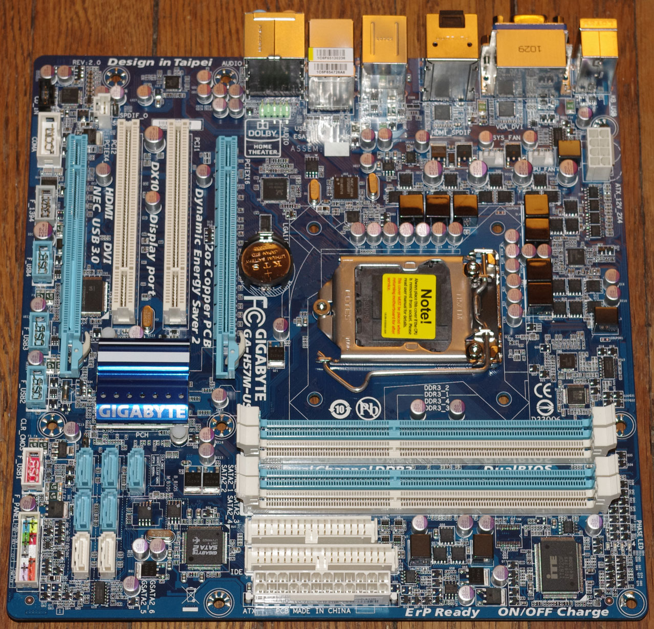
The following components are found on the mainboard::
- Microprocessor
- Chip Set
- RAM slots
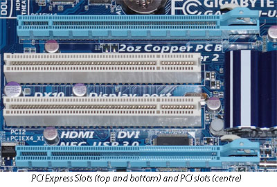
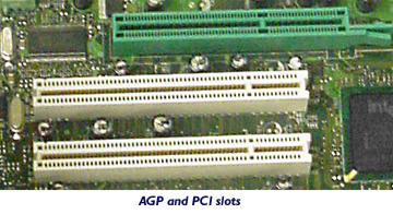
- Expansion buses
- Disk Controllers
- Basic Input/Output System
- Input/Output Ports
New: Installing the Motherboard
Typical Intel Socket 1156 Motherboard
Typical Pentium 4 or Athlon Mainboard Layout
Typical Pentium III Mainboard Layout
Basic Input/Output System
The BIOS originated when Gary Kildall sought a method of adapting CP/M to run on systems made by different manufacturers. The BIOS is a set of device drivers, some stored in ROM on the motherboard or expansion card, others loaded by the operating system. The BIOS is customized for each machine so that the operating system can complete the same tasks on different hardware.
Chip Set
 The
chip set is a group of chips which act as the interface between the microprocessor
and the rest of the devices connected to the computer. The devices found
in these chips include the clock generator, system timer, interrupt handler,
DMA controller, CMOS RAM, Real-time clock, and bus controller.
The
chip set is a group of chips which act as the interface between the microprocessor
and the rest of the devices connected to the computer. The devices found
in these chips include the clock generator, system timer, interrupt handler,
DMA controller, CMOS RAM, Real-time clock, and bus controller.
In Pentium II and Pentium III computers, the functions are contained in
two chips known as the North Bridge and the South Bridge. The North Bridge
connects the processor to main memory (RAM), the video display card (through
the AGP slot), and the PCI expansion bus. The second chip provides a bridge
from the 33MHz PCI bus to the slower devices such as ISA, IDE and USB.
The South Bridge also connects to the Super Input Output Controller chip,
which interfaces with the basic input and output ports, for attaching
external devices, including the floppy drive, keyboard, mouse, modem,
and printer.
System Clock
 All
operations in the computer must be precisely synchronized. The system
clock generates a series of pulses known as a square wave. The frequency
of the pulses is controlled by the oscillations of a tiny sliver of quartz.
Quartz crystals are used because they vibrate at a constant speed, which
depends on the size and shape of the crystal.
All
operations in the computer must be precisely synchronized. The system
clock generates a series of pulses known as a square wave. The frequency
of the pulses is controlled by the oscillations of a tiny sliver of quartz.
Quartz crystals are used because they vibrate at a constant speed, which
depends on the size and shape of the crystal.
Frequency Units
The unit of Frequency is the Hertz, named after a 19th century German physicist.
- 1 cycle per second = 1 Hertz
- 1 000 Hz = 1 kilohertz (kHz)
- 1 000 000 Hz = 1 Megahertz (MHz)
- 1000 000 000 Hz = 1 Gigahertz (GHz

It is essential that
operations within the computer be synchronized. Some events may be triggered
by the leading edge of the clock pulse, others are triggered by the trailing
edge. Clock doubling occurs when events are triggered twice in one clock
cycle.
In modern PCs different components operate at different clock speeds. The Processor, for example may operate at 2.4 GHz, while the processor bus operates at only 400MHz. The PCI bus operates at 33 MHz, but the AGP bus operates at multiples of 66MHz (1x, 2x, 4x or 8x)
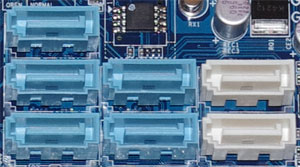
RAM slots
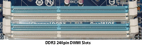
The design of RAM slots has changed many times to accomodate faster, larger capacity RAM modules. The slots shown above are designed for DDR3 Dual In-line Memory Modules (DIMM).
IDE
Interface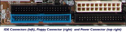
IDE (Integrated Drive Electronics) is a generic term for any hard disk which has the hard-disk controller built into the drive. The official ANSI standard is called ATA, for AT Attachment interface. IBM introduced the PC-AT, based on the 286 microprocessor in 1984. The protocols and hardware standards for connecting the hard disk drives to the AT became the industry standard, which is now controlled by an industry committee.
Under the ATA standard, hard-disks and CD-ROM drives are connected using a 40-conductor ribbon cable which plugs into a 40-pin connector on the drive and on the mainboard. Most main boards have a primary and secondary IDE connector. Servers and workstations may have additional IDE controllers using a system known as RAID (Redundant Array of Inexpensive Drives). A total of 4 drives may be connected, two on each of two cables. Each drive must be designated a master or slave using jumpers on the drive case.
As microprocessor speeds increased, the speed of the hard disk connection needed to improve to keep pace. This was achieved by modifying the ATA standard while maintaining backward compatibility with earlier versions. The newer versions are referred to as Enhanced IDE or EIDE.
One of the EIDE improvements provides faster data transfer using a method called Direct Memory Access which allows data to be moved between the hard drive and RAM without the intervention of the microprocessor. Later improvements to DMA are known as Ultra DMA, or UDMA. The latest version, UDMA 133 has a data transfer rate of 133 Megabytes per second, when used with a special 80-conductor cable.
Under the original ATA standard, the BIOS could only support drives up to 528MB capacity. The BIOS standards were revised in 1996 to accomodate drives up to 8.4 MB, and then again in 1998 to handle virtually unlimited capacities (at least by today's standards).
CD-ROM drives, digital tape drives, ZIP drives and the like use the same cables as hard disks, but the data is organized in a different format. This protocol is called the ATA Packet Interface (ATAPI). It is now part of the ATA standard.
The ATA specifications are summarized in the table below. In order to utilize the full capacity of any of these standards, all the components—chip set, disk controller, and cables—must conform to the standard.
|
Version |
Date |
DMA |
Speed |
Max.
Size |
|
ATA-1 |
1986 |
DMA |
8.33
MHz |
528
MB |
|
ATA-2 |
1995 |
DMA |
16.7
MHz |
8.4
GB |
|
ATA-3 |
1996 |
DMA |
16.7
MHz |
8.4
GB |
|
ATA-4 |
1997 |
UDMA
33 |
33.3
MHz |
136.9
GB |
|
ATA-5 |
1998 |
UDMA
66 |
66.7
MHz |
136.9
GB |
|
ATA-6 |
2000 |
UDMA
100 |
100
MHz |
144
PB |
|
ATA-7 |
2001 |
UDMA
133 |
133
MHz |
144
PB |
In February 2000 the major computer and hard drive manufacturers announced the formation of a working group to develop a new interface for disk drives to be known as Serial ATA or SATA. This standard uses seven or fifteen conductor cables and transmits one bit of data at a time at far higher clock speeds to achieve greater data throughput than ATA. Currently announced standards provide data transfer rates from 150 MB/sec to 300 MB/sec. SATA2 is now the standard connection for new hard drives.
The Small Computer
System Interface (Scuzzy) was originally adopted by Apple for the Macintosh.
It can support up to 15 devices on a single bus. Each device must have
a binary ID, set by jumpers or software, so that it can be recognized
by the controller. SCSI provides data transfer rates up to 80MB (Ultra2/Wide
SCSI) All SCSI cables require a terminator, which may be a separate device
or built into the last device in the chain.
SCSI Standards
|
MHz |
Bits |
MB/Sec |
Devices |
Pins |
|
|
Standard |
5 |
8 |
5 |
7 |
50 |
|
Wide |
5 |
16 |
10 |
15 |
68 |
|
Fast |
10 |
8 |
10 |
7 |
50 |
|
Fast/Wide |
10 |
16 |
20 |
15 |
68 |
|
Ultra |
20 |
8 |
20 |
7 |
50 |
|
Ultra/Wide |
20 |
16 |
40 |
15 |
68 |
|
Ultra2 |
40 |
8 |
40 |
7 |
50 |
|
Ultra2/Wide |
40 |
16 |
80 |
15 |
68 |
|
Ultra3 |
40
x 2 |
8 |
80 |
7 |
50 |
|
Ultra3/Wide |
40
x 2 |
16 |
160 |
15 |
68 |
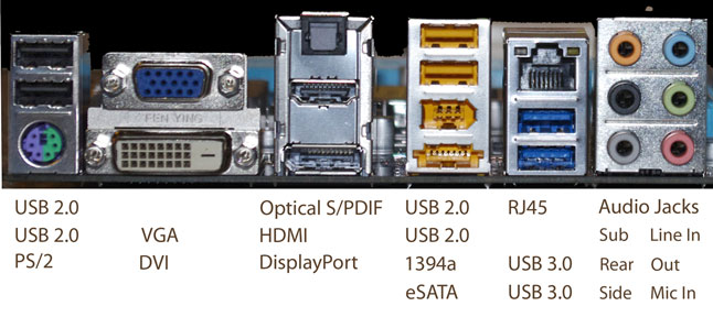
Input/Output Ports
System Resources
Hardware Interrupt Channels (IRQs) are used by most devices to signal the CPU when they have data to transmit. Only 15 are available, of which several are reserved for system timer, keyboard controller, floppy disk controller, real-time clock, co-processor, and IDE controller. Interrupt conflicts occur when two devices attempt to use the same IRQ at the same time. The PCI bus reduces interrupt conflicts by using IRQ steering to share interrupts.
DMA (Direct Memory
Access) channels are used by high-speed devices such as disk drives
and sound cards. I/O Port Addresses are the addresses assigned to the
devices connected to the bus; 64 000 addresses are available.